Saturday, October 3, 2015

[Baby Mobile Hanger] How i custom designed a Baby Mobile Hanger for our bathroom


Today i will share something sligthly different from the usual, but this is still about making something !

My baby daugther needed a little entertainment in our bathroom while she is being dressed and changed. I needed to hang a Baby Mobile that my wife made directly above the mirror. The only way i could do so was with the mural lamp that is above the mirror.

First i took precise measurements of how the lamp is and the exact dimensions that my hanger would need to be in order to fit. Here are the initial drawings


Then i went to 123D Design and sketched the item. Kept it simple


My shop printed it for me, not without trouble, i had to redo the part and removed the little hook to that the piece could be printed verticaly and not horizontaly as shown above. I would then glue the small hook back with some epoxy. Here is the final result.


With some close shots of the detail, the hook is made to fit exactly to my bathroom lamp and the little reduction of diameter at the tip is to hang the mobile using a standard key ring !


And here the final result, my little girl loves it !


Sunday, June 21, 2015

[Wireless Room Temperature Monitoring System] 3D Printed enclosure final result !

After so many weeks of inactivy (I have very good reasons i promise) i finally had the time to finish the CAD file for the enclosure and to get it printed at my local store in Alsace :)

Here is the final result. It is far from perfect unfortunately. I didnt plan for the support to get merged with some of the structure i designed. Also some of the structure were too small and had small hanging part, under which support material was still put and unfortunately ... i had to cut the whole thing to make it work. Here are a few thing that i would do differently next time :


On the left, i was too optimistic to have the small bump to guide the arduino mini pro ... unfortunately since there was hanging part over it, the bumps got merged with the support material ... i ended up remove the whole top part. Same issue with the one in the middle ... the support material added by the 3D printing software screwed the print. On the right, i made a different mistake to put the screwing hole for the temperature sensor above a another guide... i didnt plan for the support material for the screwing hole to merge with the structure below ...

Here are the pictures of the final result ! Let me know your thoughts or suggestions !

From aboce
With the components

With the lid
Without the lid 

Sunday, April 19, 2015

[Wireless Room Temperature Monitoring System] Enclosure for wireless temperature sensor 3D Modeling with 123D Design

Now that the components are all designed in 3D i can try an design the enclosure.

I tried to take into account the way the elements are going together, how the cables are connecting the components and all. I am not even sure this could be 3D printed. Here is what i intend to send for printing :


What do you think ? Any suggestions ?

Thursday, April 9, 2015

[Wireless Room Temperature Monitoring System] Enclosure for wireless temperature sensor 3D Modeling with 123D Design

Alright so now that i have a rough idea of how the enclosure should be i can go ahead and design it in CAD. 123D Design seems perfect and easy to use. As a training exercice I decided to reproduce all the components that are involved in my sensor in 123D Design at the exact correct scale. This way i will be able to design the enclosure to take into account. First i took exact measurement of each of the 5 main components that are involved in the sensor.

Here is how it looks :


What do you think ?  Any advice ?

If anyone is interested for their own CAD design (and if you use the same components as me ...) please contact me and i will give you the .stl file

Next, i will make the enclosure using those components to make sure that everything fits together


Saturday, March 28, 2015

[Wireless Room Temperature Monitoring System] Enclosure for wireless temperature sensor prototype

Alright, so now that i have to mess up with the code and make the code work properly, i need to have an easy to handle hardware prototype. To do so i incorporated a switch so i can put the sensor on and off without having to unplug the battery.

There it is :  The switch is available on the front side. I made a hole to have the temperature sensor stick out of the box for more accuracy.

View of the inside... pretty messy but it works


And there it is closed, the antenna is sticking out of the box through  a hole.


Until I design a 3D printed enclosure, that will do the trick. 


Monday, March 23, 2015

[Wireless Room Temperature Monitoring System] Labeling a temperature (DS18B20) from an Arduino Pro Mini to a Raspberry Pi

Back to square 1. Unfortunately the code i have been using since the beginning to send the data from the Arduino to the Raspberry Pi.

Thanks to smart people on the internet i found out there was a way to have an Arduino talk to a Raspberry Pi using the VirtualWire libraries (initially made for only Arduino to Arduino communications).

1) The Arduino part :

Download and Install the VirtualWire library : Information // Dowload Link

I uploaded the following code to my Arduino Pro Mini:
#include <VirtualWire.h>
#include <OneWire.h>
#include <DallasTemperature.h>
#define ONE_WIRE_BUS 3 //DS18B20 Connected to Pin 3

int compteur = 0;

const char *msg = "Temp1 ";
const char *celsius = "C: ";
const char *diese = " #";
char nombre[VW_MAX_MESSAGE_LEN];
char message[VW_MAX_MESSAGE_LEN];
char tempCx100char[VW_MAX_MESSAGE_LEN];
OneWire oneWire(ONE_WIRE_BUS); // For the DS18B20
DallasTemperature sensors(&oneWire);
DeviceAddress Thermometer = { 0x28, 0xFF, 0xED, 0x0F, 0x11, 0x14, 0x00, 0xD2 }; //Obtained using another program
void setup()
{
   Serial.begin(9600);  // Debugging only
   sensors.begin();
   sensors.setResolution(Thermometer, 10);
 
   // Initialise the IO and ISR
   vw_set_tx_pin(10);
   vw_set_ptt_inverted(true); // Required for DR3100
   vw_setup(2000); // Bits per sec
}
void printTemperature(DeviceAddress deviceAddress)
{
  compteur++;

  float tempC = sensors.getTempC(deviceAddress);
  int tempCx100 = (int)(tempC*100); // Multiply the float value to have a full int with 2 digits
  itoa(tempCx100,tempCx100char,10); //Convert int to char
  itoa(compteur,nombre,10); // compteur de message

  strcpy (message,msg);
  strcat (message,tempCx100char);
  strcat (message, diese);
  strcat (message,nombre);

  if (tempC == -127.00) {
    Serial.print("Error getting temperature");
 
  } else {
    digitalWrite(13, true); // Flash a light to show transmitting
    vw_send((uint8_t *)message, strlen(message));
    vw_wait_tx(); // Wait until the whole message is gone
    digitalWrite(13, false);
  }
}
void loop()
{
  sensors.requestTemperatures();
  printTemperature(Thermometer);
  Serial.print(message);
  Serial.print("\n\r");
  delay(1000);
}

I basically compiled all the DS18B20 related codes i found out about earlier along with the specific code available to send stuff from VirtualWire library.
The code is sending a message with
    - a string that enables me to identify which temperature sensor sends the message.
    - the temperature as a 4 digit integer (2125 > 21.25C)
    - a message count in order to follow which messages are being lost for prototyping purposes

2) The Raspberry Pi part :

I basically used a python code suggest by this Joan on the raspberry pi forum : Link
You also need the pigpio library to be installed on the RPi : Link
wget abyz.co.uk/rpi/pigpio/pigpio.zipunzip pigpio.zipcd PIGPIOmakemake install
The code (vw.py) is a massive program which allows me to either receive or send using the RF433 Module : Link

I copied the program file in a dedicated folder on the Raspberry Pi along with another python program that will import the vw.py and once started, will only do what i need it to be doing
import timeimport pigpio
import vw
RX=27
BPS=2000pi = pigpio.pi() rx = vw.rx(pi, RX, BPS) start = time.time()print("En attente de la reception des donnees")
while (time.time()-start) < 100: while rx.ready(): print("".join(chr (c) for c in rx.get()))rx.cancel()
pi.stop()
 The result :

The Arduino Pro Mini with DS18B20 + TX433 and the relevant code is plugged in, and i start the program above and here the result :


It works ! :) Thank you to all contributor in the internet for their python programs and other libraries !

Now i can identify each temperature sensor. Next i will probably build another sensor module and try to receive both temperature and see if they don't interact too much and create a mess :)

Sunday, March 1, 2015

[Wireless Room Temperature Monitoring System] Sensor Enclosure Prototyping Part 1

I have been doing some thinking on the enclosure i want to 3D Print myself.

The goal is to have a relatively simple design to store all modules : Arduino, Temperature sensor, 9V Battery enclosure and TX RF 433 Mhz Module.

Here are the first prototype drawings :


I am already having second thoughts about the enclosure, specifically about the antenna. My latest test showed that i should have a linear antenna instead of a coiled one...

I will have some more drawing done in the following days.


Friday, February 27, 2015

[Wireless Room Temperature Monitoring System] Sending Temperature values to the Raspberry Pi and store it in a .txt file

Now that each elements are working independently we will have the arduino measuring the temperature, sending it with the TX 433 Mhz module through the air and have the Raspberry Pi pick up the data and collect it in .txt file

I had to modify the Arduino code in order to get the temperature with full details. The device is giving a float value that cannot be sent over RF (basically we loose the numbers after the comma). In order to avoid that we multiply the float value by 100 in order to get full details and send it over RF.

I modified the "printTemperature" class from the Arduino Code :
void printTemperature(DeviceAddress deviceAddress)
{
  float tempC = sensors.getTempC(deviceAddress);
  int tempCx100 = (int)(tempC*100); // Multiply the float value > int with 4 digits

  if (tempC == -127.00) {
    Serial.print("Error getting temperature");
    mySwitch.send(0000, 24);
  } else {
    Serial.print("C: ");
    Serial.print(tempC); //reads the temp value on the serial port
    mySwitch.send(tempCx100, 24); //Temperature x100 with all the accuracy needed
  }
}
On the receiving end, I modified the code in order to modify the received Int into a float and to store the value received in a file.

Modification of the while loop within the RFSniffer.cpp program
 while(1) {
      if (mySwitch.available()) {
        int value = mySwitch.getReceivedValue();
        float valuefloat = (float) (value/100.0); // Divide the received value to get a float
        if (value == 0) {          printf("Unknown encoding");        } else {
          printf("Recu %i\n", mySwitch.getReceivedValue() );
          FILE *f = fopen("/home/pi/recu.txt", "a"); //append the value within the next line of the recu.txt file          fprintf(f,"%i\n",value );
          fclose(f);        }
        mySwitch.resetAvailable();
      }
There you can see the reading directly on the Serial Port reader from the Arduino Software


Then there is the value being sniffed by the Raspberry Pi directly in the Terminal


And finally the content of the file in which we are appending the received file indefinitely

Now that this work, here are the next challenge.

I need to be able to "identify" which Temperature sensor sent this result, basically label the sent value
I need to append those values into a file per day with the time stamp available
Ultimately i should be able to have those values read and plotted in a graph.

Friday, February 13, 2015

[Wireless Room Temperature Monitoring System] Temperature sensing with DS18B20 sensor and Arduino Pro Mini

The goal here is to plug the DS18B20 Temperature sensor to the Arduino Pro Mini.
For my project i decided to go with an already complete module with the sensor as well as the 4,7 kOhms ... less soldering !

The wiring : 

The DS18B20 Module has 3 pins just like the DS18B20 sensor alone.

      DS18B20 Module > Arduino Pro Mini

  • - (Negative) > GND
  • + (Positive) > VCC
  • Data > Pin 3 


The software :

Once the wiring is all done, the next step is to try finding out what is the address of the sensor in order to get the temperature measure later on.

You need to install the OneWire and the DallasTemperature libraries
- One wire : http://www.hacktronics.com/code/OneWire.zip
- DallasTemperature : http://www.hacktronics.com/code/DallasTemperature.zip

The idea is to upload the following code to the Arduino Pro Mini with the sensor wired :
#include <OneWire.h>
#include <DallasTemperature.h>
OneWire  ds(3);  // Connect your 1-wire device to pin 3
void setup(void) {
  Serial.begin(9600);
  discoverOneWireDevices();
}
void discoverOneWireDevices(void) {
  byte i;
  byte present = 0;
  byte data[12];
  byte addr[8];

  Serial.print("Looking for 1-Wire devices...\n\r");
  while(ds.search(addr)) {
    Serial.print("\n\rFound \'1-Wire\' device with address:\n\r");
    for( i = 0; i < 8; i++) {
      Serial.print("0x");
      if (addr[i] < 16) {
        Serial.print('0');
      }
      Serial.print(addr[i], HEX);
      if (i < 7) {
        Serial.print(", ");
      }
    }
    if ( OneWire::crc8( addr, 7) != addr[7]) {
        Serial.print("CRC is not valid!\n");
        return;
    }
  }
  Serial.print("\n\r\n\rThat's it.\r\n");
  ds.reset_search();
  return;
}
void loop(void) {
  // nothing to see here
}
code source : http://www.hacktronics.com/Tutorials/arduino-1-wire-address-finder.html

Once up and running with the program in the Arduino, go to :

Tool > Serial Monitor.

The sensor address will then show up on the monitor. In my case it was :
0x28, 0xFF, 0xED, 0x0F, 0x11, 0x14, 0x00, 0xD2 
With this address we can move on to the next and final step, measure some temperatures finally !
Upload the following code to the Arduino Pro Mini
#include <OneWire.h>   
#include <DallasTemperature.h>
// Data wire is plugged into pin 3 on the Arduino
#define ONE_WIRE_BUS 3
// Setup a oneWire instance to communicate with any OneWire devices
OneWire oneWire(ONE_WIRE_BUS);
// Pass our oneWire reference to Dallas Temperature.
DallasTemperature sensors(&oneWire);
// Assign the addresses of your 1-Wire temp sensors.
DeviceAddress Thermometer = { 0x28, 0xFF, 0xED, 0x0F, 0x11, 0x14, 0x00, 0xD2 };
void setup(void)
{
  // start serial port
  Serial.begin(9600);
  // Start up the library
  sensors.begin();
  // set the resolution to 10 bit (good enough?)
  sensors.setResolution(Thermometer, 10);
}
void printTemperature(DeviceAddress deviceAddress)
{
  float tempC = sensors.getTempC(deviceAddress);
  if (tempC == -127.00) {
    Serial.print("Error getting temperature");
  } else {
    Serial.print("C: ");
    Serial.print(tempC);
    Serial.print(" F: ");
    Serial.print(DallasTemperature::toFahrenheit(tempC));
  }
}
void loop(void)
{
  delay(2000);
  Serial.print("Getting temperatures...\n\r");
  sensors.requestTemperatures();

  Serial.print("Inside temperature is: ");
  printTemperature(Thermometer);
  Serial.print("\n\r");
}
Code source : http://www.hacktronics.com/Tutorials/arduino-1-wire-tutorial.html

Once the Arduino is running the program, go to the Serial Monitor again.
The temperature should be printed on the screen


Tada ! Temperature is displayed on screen !

Next step is to try and combine the temperature sensing and to send it via TX 433 Mhz to the Raspberry Pi to sniff !

If anyone has any idea on how to do that ... i am interested !

[Wireless Room Temperature Monitoring System] Sending a value through RF 433 Mhz Module from an Arduino Pro Mini 5V

Now that i have successfully programmed the Arduino Pro Mini with a simple blink program, i need to take it to the next level and try to send some data through the TX 433 Mhz module.

For the wiring :

The TX 433 Mhz pin are to be connected as following:

  • VCC > Any VCC pin on the Arduino Pro Mini
  • GND > Any GND pin on the Arduino Pro Mini
  • Data > Pin 10 on the Arduino Pro Mini
Here i am using the FT232RL module to power the Arduino Pro Mini, but ultimately i will plug a 9V Battery as source of power


Now from the Software side :

First download and install the RCSwitch library : https://code.google.com/p/rc-switch/

Once done you can compile and send the following code to the Arduino Pro Mini

Sending data code :
#include <RCSwitch.h>

RCSwitch mySwitch = RCSwitch();

void setup() {
  Serial.begin(9600);
  // Transmitter is connected to Arduino Pin #10
  mySwitch.enableTransmit(10);

  // Optional set pulse length.
  // mySwitch.setPulseLength(320);

  // Optional set protocol (default is 1, will work for most outlets)
  // mySwitch.setProtocol(2);

  // Optional set number of transmission repetitions.
  // mySwitch.setRepeatTransmit(15);

}

void loop() {
  /* Same switch as above, but using decimal code */
  mySwitch.send(5393, 24);
  delay(1000);
  mySwitch.send(5396, 24);
  delay(1000);

  /* Same switch as above, but using binary code */
  /*mySwitch.send("000000000001010100010001");
  delay(1000);
  mySwitch.send("000000000001010100010100");
  delay(1000);*/

  delay(2000);
  //mySwitch.send(4212181, 24);

}
Note this code is not from me at all. source : http://www.homautomation.org/2013/09/21/433mhtz-rf-communication-between-arduino-and-raspberry-pi/

On the receiving end, we have the RX 433 Mhz module plugged in the Raspberry Pi (Receiver : Pin 13 (GPIO 27 Rasp Pi B+). Also marked as Pin 2 under WiringPi's naming convention)

I am basically using the same setup (RFSniffer code etc ...) as explain in the following post : Link

And it works ! The Raspberry Pi successfully sniffs the code sent (5393, 5396)


Looks like that all the send messages were not picked up, only 1 within the loop (4 digit long) the other two are longer and i am not sure they are being picked up by the RFSniffer program.

Yay, that is big for me that is not an electronic expert :)

Next i will try to make the DS18B20 independently with the Arduino Pro Mini

Thursday, February 12, 2015

[Wireless Room Temperature Monitoring System] Program the Arduino Pro Mini through USB Serial FT232RL Module

First step to work on an Arduino Pro Mini project is to actually manage to program the processor in order to have it behave the way you want.

The wiring :

From FT232RL to Arduino Pro Mini the wiring is done as following :

      FT232RL > Arduino
  • DTR > DTR
  • RX > TXD
  • TX > RXD
  • VCC > VCC
  • CTS > GND
  • GND > GND
Then the FT232RL is connected to my Macbook Pro through USB Mini


The software / computer :

Install all the necessary drivers to allow the mac to use the FT232RL USB Serial : http://www.ftdichip.com/Drivers/VCP.htm (version 2.2.18 for Mac OS X)

Install the Arduino software : http://arduino.cc/en/pmwiki.php?n=main/software

At first i couldn't have a successful connection between the computer and the Arduino but after some trial and error here are the different settings/selections within the software :

Tools > Board > Arduino Pro or Pro Mini (5V, 16Mhz) w/ ATmega328
Tools > Serial Port > /dec/cu.usbserial-A50285BI (which i assume is the reference of my FT232RL)
Tools > Programmer > Arduino as ISP

I threw in a small blinking led program to test if the code went through :

// the setup function runs once when you press reset or power the board
void setup() {
  // initialize digital pin 13 as an output.
  pinMode(13, OUTPUT);
}
// the loop function runs over and over again forever
void loop() {
  digitalWrite(13, HIGH);   // turn the LED on (HIGH is the voltage level)
  delay(50);              // wait for a second
  digitalWrite(13, LOW);    // turn the LED off by making the voltage LOW
  delay(50);              // wait for a second
}
code source : arduino software example library

After verify the code, i then upload the sketch to my Arduino Pro Mini, here is the result :


And, bim the light is blinking fast ! Upload successful


Tuesday, January 27, 2015

[Wireless Room Temperature Monitoring System] How to test the 433 Mhz RF Module (Receive / Transmitter)

I started to receive some of the parts that i ordered. Unfortunately i didn't receive enough to start the project.

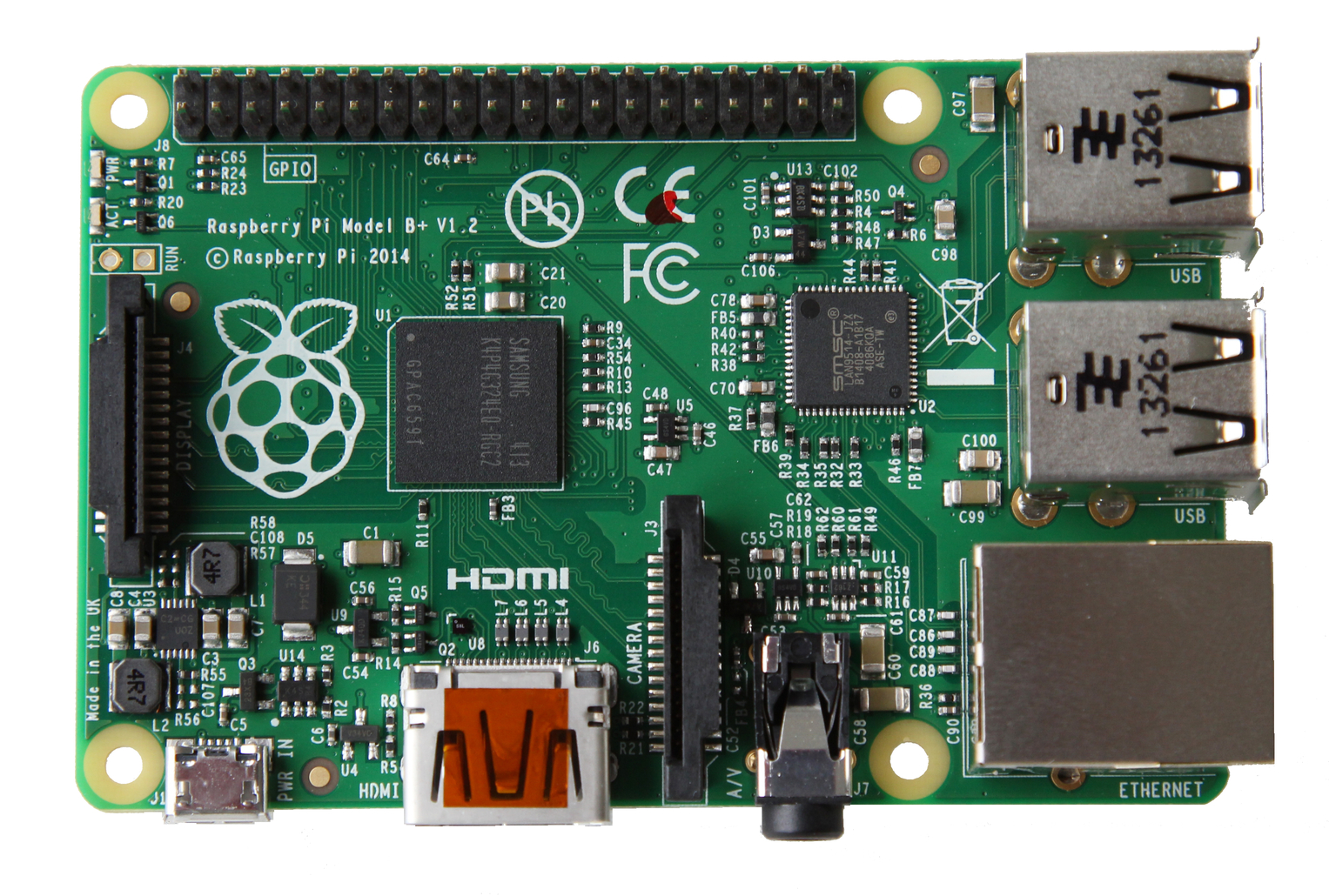
Fortunately what i received already can be tested. I received my 5 pairs of RF 433 Mhz modules (RX / TX), jumper cables and some small breadboard, with the Raspberry Pi i already had ... i can cook :)

The idea here is to be able to test the modules in order to see if all 5 pairs work properly (since they were crazy cheap and sent from China)

The strategy here is to use the Raspberry Pi as the sender and the receiver.

First i had to install WiringPi in order to have the GPIO working properly
Then i had to install 433Utils, a neat little module that is allowing me to receive (sniff) and send data.

For the wiring i use a breadboard to power both RX and TX modules using the 5V pin 2 and the GND pin 6.
Then i use cables to connect the RX/TX modules data pins :

  • Emitter : Pin 11 (GPIO 17) of the Raspberry Pi. Also marked as Pin 0 under WiringPi's naming convention)
  • Receiver : Pin 13 (GPIO 27 Rasp Pi B+). Also marked as Pin 2 under WiringPi's naming convention)

With that simple setup on i can go ahead i can try and send data and see if it is being received.

Now on my computer i connect to my Raspberry Pi using ssh
Code 1 : ssh pi@yourlocalIPaddress  (once prompted, enter your password. Default is "raspberry") 
Then i have to go to the specific folder where the 433Utils programs are stored in order to start them.
Code 2 : cd 433Utils/RPi_utils
This bring you to the correct folder where the sending program and the sniffing program are stored.
Now i open another Terminal window and login via ssh (code 1) and i go to the 433Utils folder (code 2)

In the first terminal window start the Sniffer program.
Code 3 : sudo ./RFSniffer
Now in the second terminal window send a code
Cod 4 : sudo ./codesend 121234 (any random integer)
If everything works fine, you should see your integer going through the Sniffer result window just like in the below screenshot :


I noticed that i couldn't send more than 8 digits for that integer.

This is my first victory with this stuff that i never used before as i am not in electronics at all.

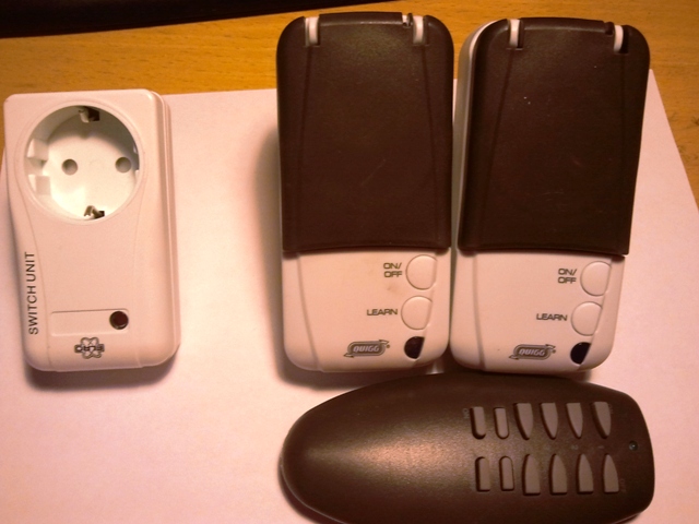
Now i have been trying to mess-up with it and tried to "sniff" different 433Mhz RF Remotes in order maybe to know what was the sent signal and use the Rasp Pi as a replacement remote.

I tried with 2 differents things. 

  • A RF wall plug remote (Brand QUIGG), the user can't really do anything with the remote (no channel selection or anything like) ... whatever i tried ... no signal was picked up.
  • A RF Remote for an automated garage door from my building. Same thing here ... no luck in picking the signal from the remote ...


I read in many place that the only of "reading" the signal from a remote was to use a jack and soundcard in order to "see" the pattern of the signal and reproduce it. Anyone have any idea how this works ?


Monday, January 19, 2015

[Wireless Room Temperature Monitoring System] The plan

Now that all the parts are ordered i am basically waiting.

I decided to utilize that time and draw a small sketch of how i plan to connect the multiple elements of my project. Basically it looks like that
Key
Orange = positive current
Lines = negative
Stripes = data


What do you think ? Am i making any mistakes ?

Friday, January 9, 2015

[Wireless Room Temperature Monitoring System] Component Choice

In order to build the system i thinking of using the following :

For the sensor :

  • Arduino Mini Pro 5v


  • DS18B20 Module for temperature detection


  • Emiter RF 433 Mhz

  • Antenna
  • 9V Battery Case
For the computing system :
  • Raspberry Pi B+


  • Receiver RF 433 Mhz

  • Antenna
  • Wall Plug Power Source
  • Wifi Dongle
In order to program the Arduino Mini Pro i think i will go with a USB to TTL serial adapter FT232RL.
I am about to order all those parts online...